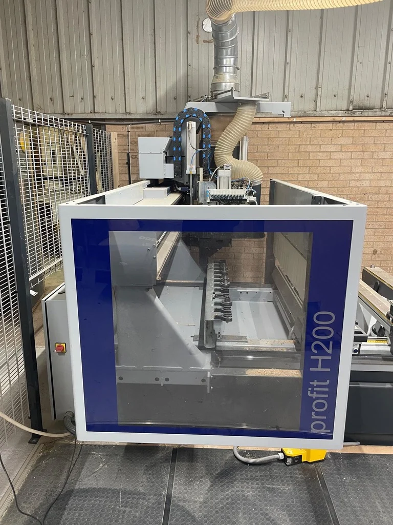
Description
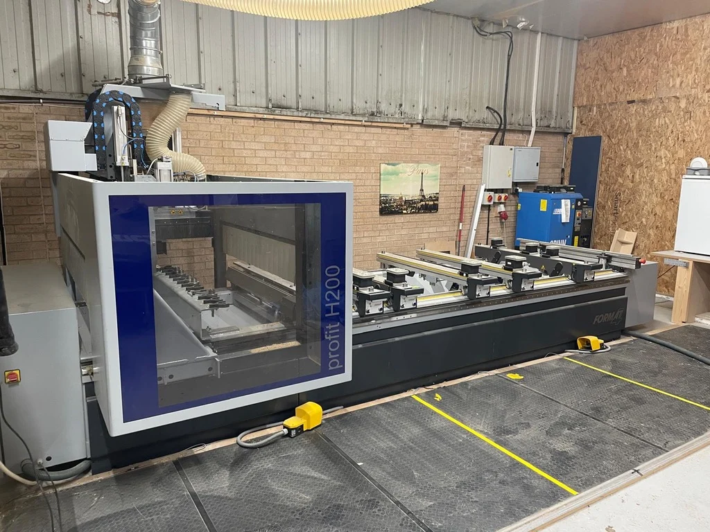
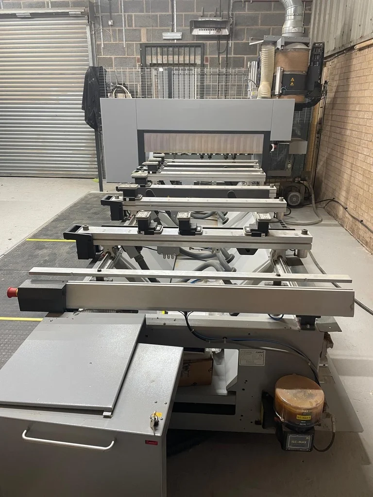
CNC machining centre profit H200 13.33
Machine Serial No.: 302.02.011.18
Profit H200 13.33 electrical connection:
3x400V 50Hz / 60Hz
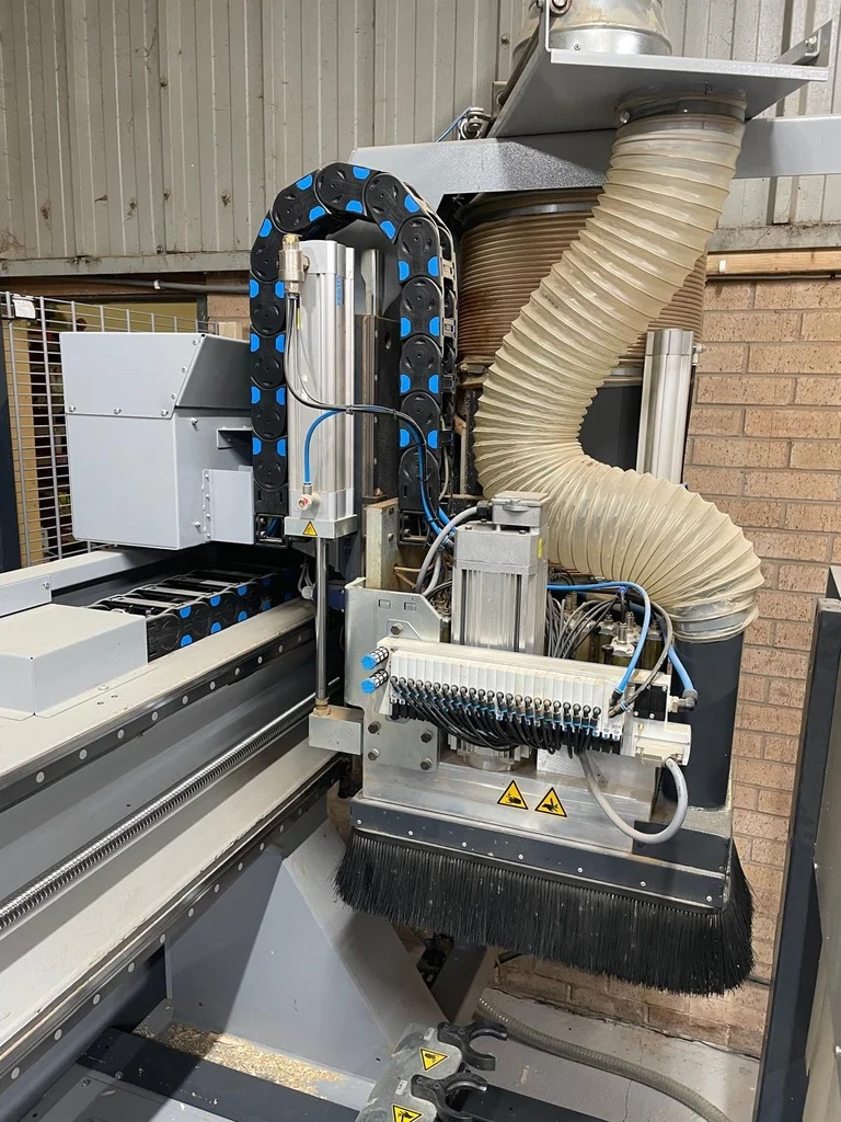
12 kW (S6) main spindle HSK F63 24,000 rpm, ceramic bearings with pneumatic height adjustment of the extraction hood to 2 positions:
Power requirement: 12 kW (S6)
Maximum performance at ca. 12000 rpm
Rotating speed: 1000 – 24000 rpm
Drive: 3-phase HF motor, inverter-controlled rotation: left/right, 2 controlled compressed air connections, interface for aggregates,
Tool weight (rotating): 7.5kg
Spindle cooling: air cooled
Extraction hood with 2 positions
Profit H200 13.33:
CNC machining centre with gantry design (without tools) with digital drive (driven on one side). The machine chassis of the profit H200 13.33 is made from thick walled electrically welded shaped tubes. The steel ribbing inside the chassis ensures a high level of stability.
Working field H200 13.33:
Travel distance of the axis: X= 4000 mm
Y= 1670 mm
Z= 500 mm
Working area:
X= 3300 mm
Y= 1280 mm
Z= 250 mm passage height (from the level of the consoles), depending on the clamping system Axes positioning speeds: As determined by the selected safety systems
Single side driven gantry
X-axis guiding system:
The drive of the gantry along the X axis is carried out using a rail with angled, cambered teeth. This guarantees maximum precision. The reduction gearing ensures maximum processing quality and repeatability. Positioning is carried out by recirculating ball bearings running along hardened and polished linear guides.
Y-axis guiding system:
Positioning is carried out by recirculating ball bearings running along hardened and polished linear guides. The Y axis is positioned by a polished recirculating ball spindle.
Guiding system Z-axis:
Positioning is carried out by recirculating ball bearings running along hardened and polished linear guides. The Z axis is positioned by a polished recirculating ball spindle.
Automatic central lubrication system:
The lubrication is applied as and when required to the guide carriages of the X, Y and Z axis as well as the bearing spindles in Y and Z. Lubrication is carried out automatically after a pre-set time.
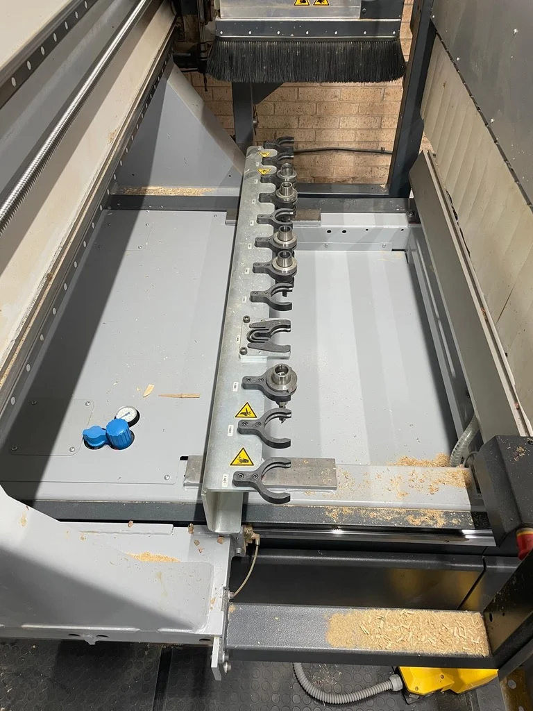
12 position linear tool changer on the left of the machine chassis, incl. one pickup position for aggregates:
The 12-position tool changer ensures quick changeover times and more than adequate space for milling tools.
One aggregate position
Max. tooling diameter 250 mm Max. tooling length 240 mm
Centrally controlled extraction connection:
The program control controls the extraction to either the drilling head or main spindle. The controlled gate ensures an optimum extraction performance. Connection diameter see layout
Positioning display of consoles and vacuum pods:
The workpiece, the consoles and the vacuum pods are all shown in the CNC Board simultaneously. This guarantees that the workpiece is positioned securely and that there can be no collision between the tooling and vacuum pods. The exact position of the vacuum pods on the console is displayed using a laser.
Vacuum connection for template milling on the left-hand side of the machine Vacuum system 90mn/h:
1 vacuum pump with a total vacuum capacity of 90 mn/h / 50 Hz, 108 mn/h / 60 Hz
Performance specifications of the machine software Woodflash:
The machine software package Woodflash includes the complete control management of the CNC machine for 2 workstations – 1 on the machine and 1 external workstation. The software consists of: -CNC board
-Tooling database:
– Program editor
CNC board:
The overall operation of the machine is done via the CNC board. This is where it is possible to load existing programs and run them. As an example, it is also possible to select various working fields, save customer specific processing lists or use a zoom function. The control of diverse machine sensors (compressed air, safety devices, display of the feed speed, etc.) is also carried out using the CNC Board as well as the selection of pre-programmed machine commands (unloading tools or warming up of the axes, etc.).
Tooling database:
In the tooling database (Tecno-manager) all of the tools that have been defined for processing on the machine can be edited. The primary classification is split into the 3 categories drilling, milling and sawing. They are then subdivided into the respective processing face (vertical and horizontal). Parameters such as tool length, diameter, max. drilling depth, rotation speed can be set here. The tool contours can also be defined with the help of DXF files using this database.
Programming editor:
The program editor is used to create custom CNC programs. Using the help of the available variable macros it is possible to create parametric processes. The simple and clear layout enables quick
drilling, milling and sawing processes. There are five individual sides available for programming. To check a program, it is also possible to change to a 3D view,
Additional functions:
-CAD-commands (rotate, mirror, repeat, etc.) -Font milling (TrueType Font, bold or italics) -Clearing of any contours (pocket milling) -Scaling of contours
-Set logical conditions
-Save variables (max. 300)
-Milling interpolation
-Virtual surfaces in every position
-Sub-programs (self-created programs)
-Sort sequences (optimisation of processing time) -Absolute or relative programming
Hand-held terminal for the control of the axis speed including emergency stop switch:
A potentiometer makes it possible to have variable control of the feed speed whilst processing. As a result, this helps to make the processing of complex programs much easier.
– Safety system with light barrier at the front of the machine – Emergency off switch
– Safety fence on left side of the machine
– Secured door
– Control sensors for the vacuum and air
Safety fence on left side of the machine
Uninterruptible power supply (UPS):
The UPS guarantees power to the machine computer even in the event of a power cut. Programs can be saved and the machine computer shut down as normal, without loss of data.
2 continuous rows of fences in the Y direction:
Mounted to the cylinder stops on the left and right end of the working field
0-360° C-axis for the main spindle:
Fourth axis on the main spindle. Precision gear drive 0-360° The C-axis enables the use of aggregates.
4 position linear tool changer moving in X:
Tool changer for 4 milling tools or aggregates, mounted to the gantry. (See layout for configuration options)
Maximum tool diameter 250 mm
Maximum tooling length 300 mm
6 instead of 4 consoles:
With front and rear rows of fences. Hose-free vacuum dual circuit system with vacuum pod height 100mm. Pneumatic locking of the consoles that run on hardened and polished round bars. A front and rear program controlled, pneumatic cylinder, on each of the consoles. 4 moveable side fences in Y direction. 4 loading supports make it easier to load or unload large/heavy workpieces. Load capacity of each of the support is 20kg.
Safety system with safety mats incl. pendulum operation instead of light barriers:
Pendulum operation with two-foot pedals and a second vacuum connection for template milling on the right-hand side of the machine
Controlled compressed air connection for frame clamps (6 consoles):
All of the compressed air frame clamps on the working field can be opened/closed simultaneously using the foot pedal. The vacuum required to hold the frame clamps in place remains. There are 3 compressed air connections on each of the consoles.
Vacuum and compressed air activation for 6 consoles:
This enables the individual manual repositioning of vacuum pods/frame clamps on the individual consoles or the removal of off-cuts, whilst the workpiece remains held in position.
DH24 6H 2S drilling head:
18 vertical spindles
12 spindles in X direction and 6 spindles in Y direction.
6 horizontal spindles:
4 spindles in X direction and 2 spindles in Y direction.
Pre-lift = 70 mm, max. drill length = 70 mm and shaft D = 10 mm.
All spindles can be used independently.
2 grooving saws – one each in X and Y direction, max. saw blade diameter 120 mm, max. blade thickness 5 mm, max. speed variable up to 7500 rpm. The drilling head covers the whole working field, with both the horizontal and vertical drills.
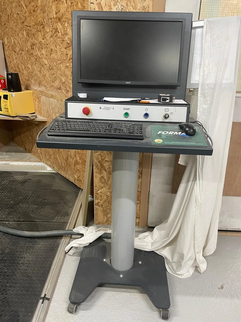
Mobile operating terminal Equipped with:
– 24″ LED colour display screen
– Keyboard, mouse and mouse pad – 1 USB Port
4 axis interpolation with the C axis, including 0-point tilt (at the tip of the tool). Easy control of the tilt and direction angles with visual control and individual entering of the Z application layers during milling set-up. The milling contour can be run with a fixed axis, or changed at the click of the mouse to 4 axis interpolation.